




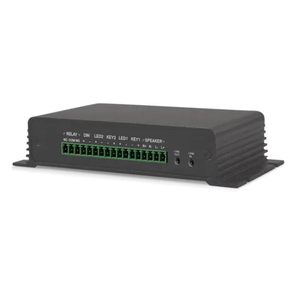
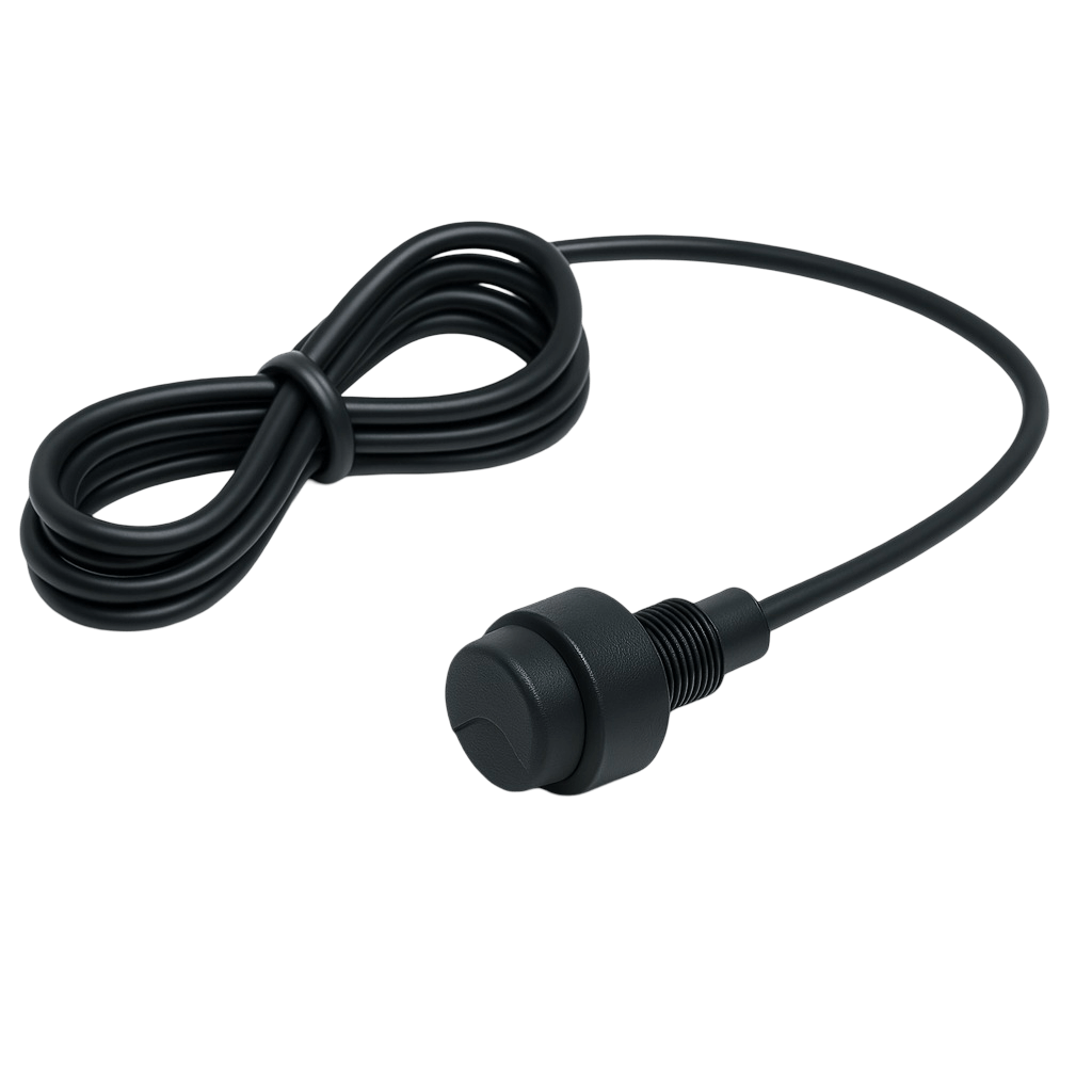
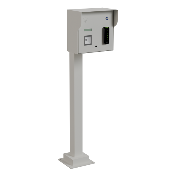

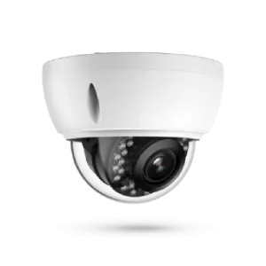
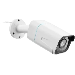
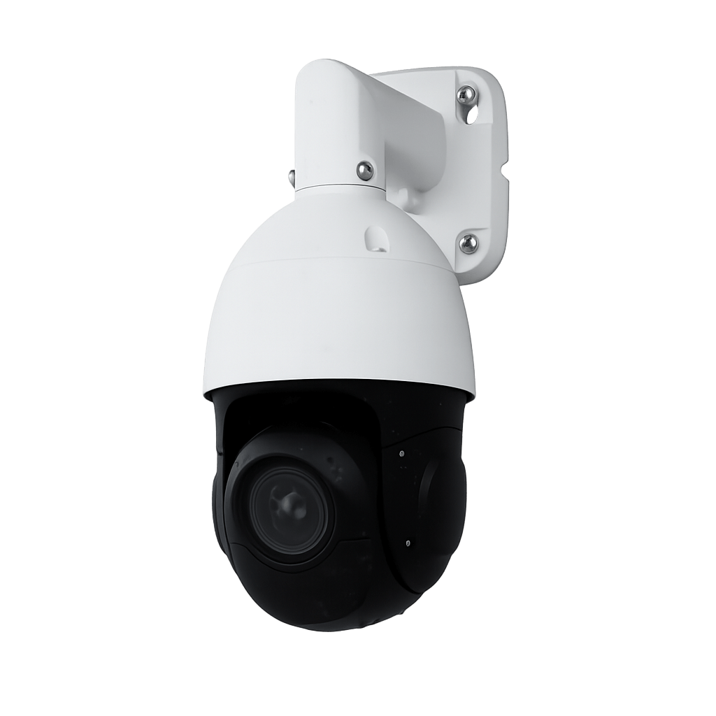
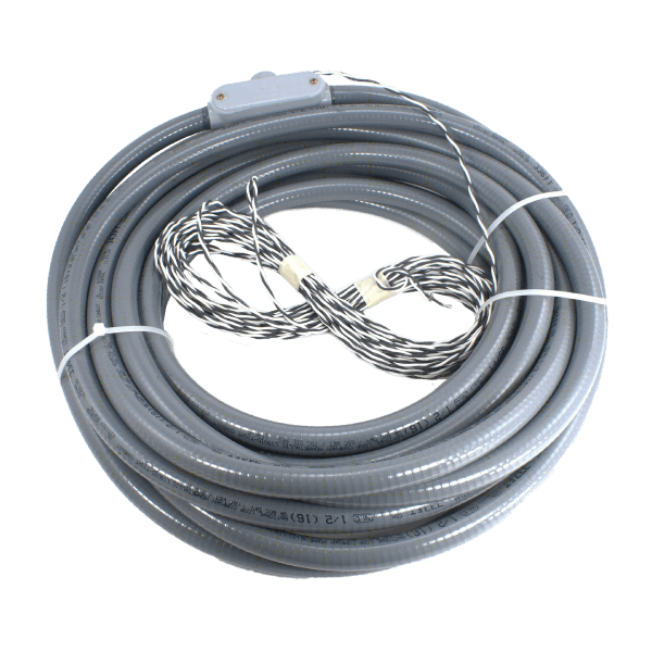
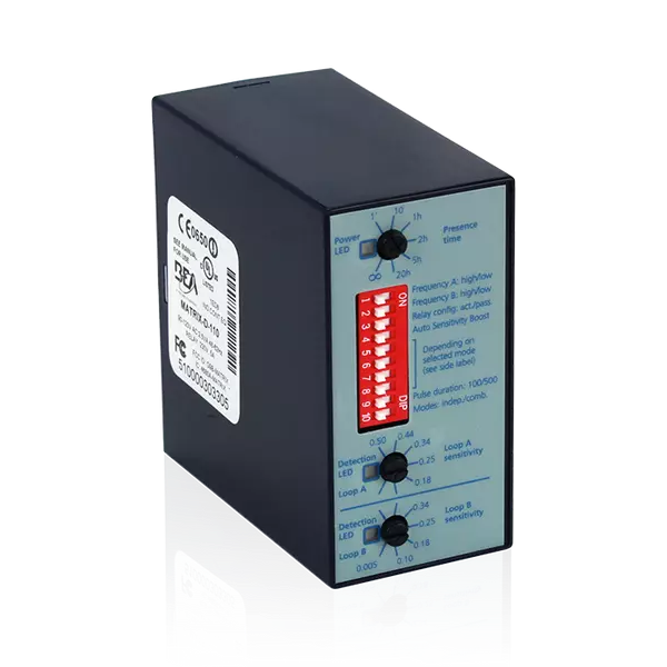
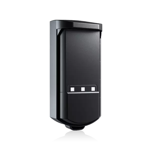
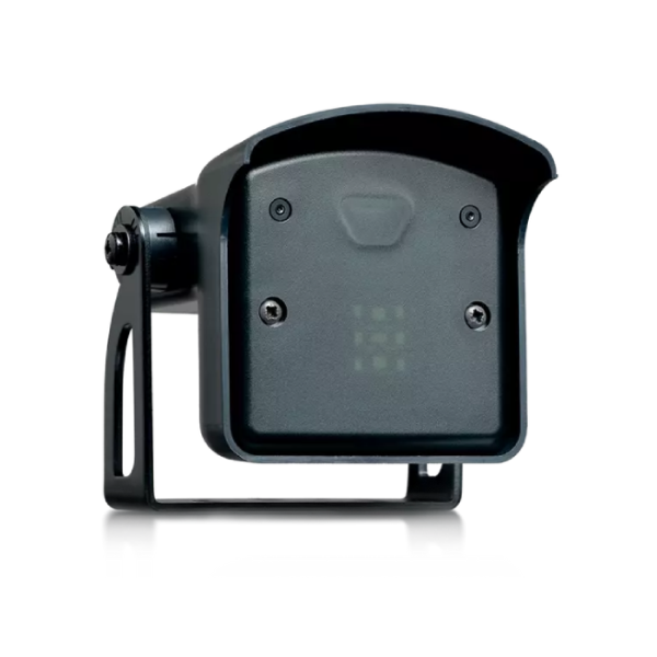
Document how an occasional delivery is identified, where its driver waits and who can authorize the passage. Compare that process with the normal staff credential sequence, including the vehicles and stopping positions involved. The barrier configuration must be assessed with both workflows; a staff access method does not automatically provide a workable delivery procedure.
Barriers and lane equipment
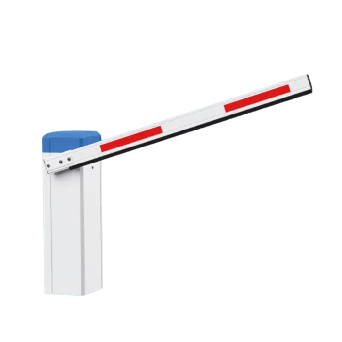
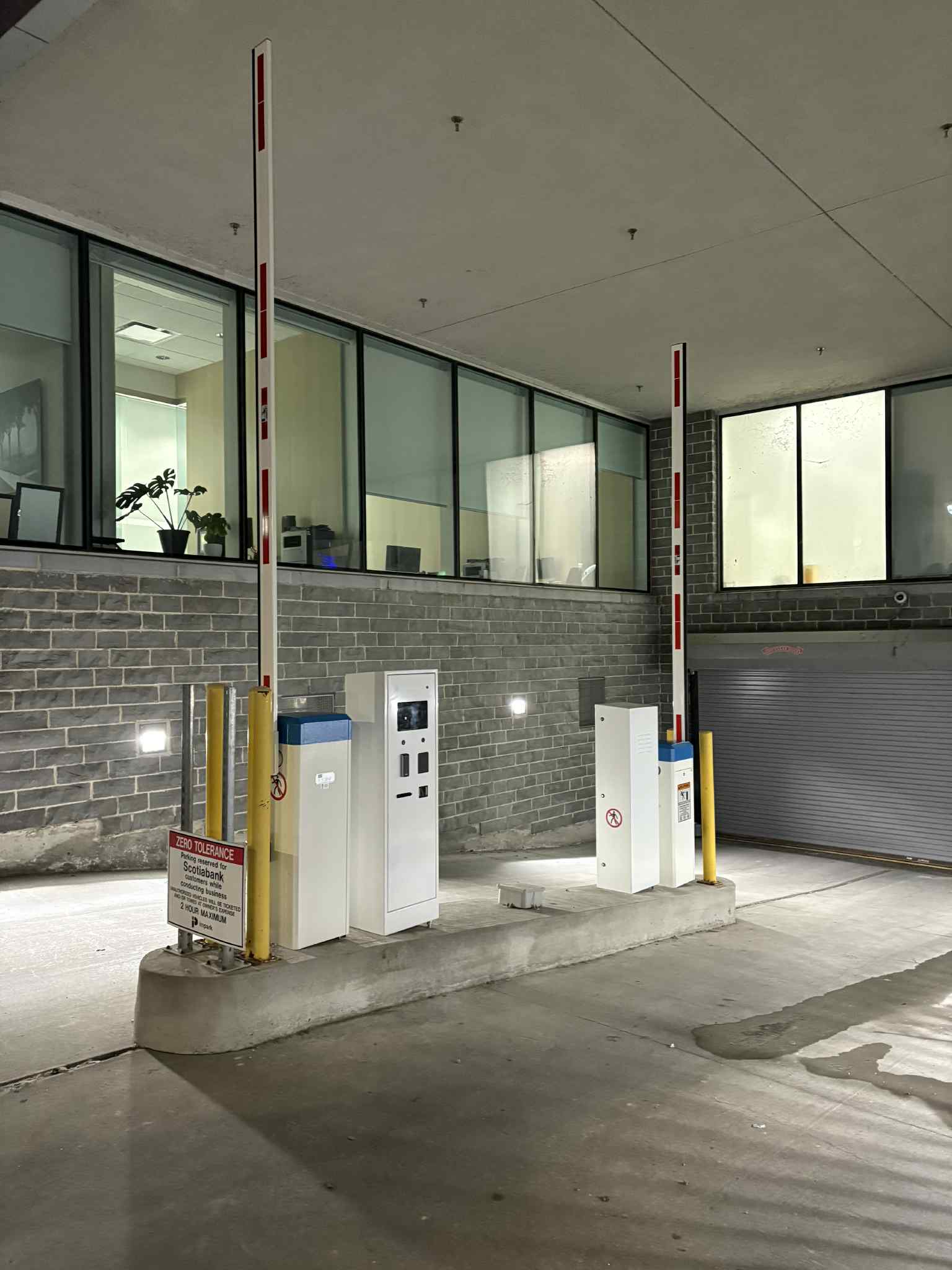
Industrial vehicle barrier
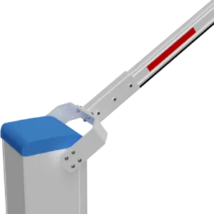
Lexoh integrates industrial vehicle barriers from ELKA, Automatic Systems and Pivin & Drapeau. Select the model, foundations and controls around your vehicles, traffic and operating environment. Any required impact resistance must be documented for the exact model.
- Role
- Controlled vehicle lane
- Manufacturers
- ELKA · Automatic Systems · Pivin & Drapeau
- Configuration
- Selected for your site
Application first
Choose the barrier for the vehicles and the site.
An industrial entrance brings vehicle clearance, foundations, operating demand and access procedures into the same equipment decision.
Industrial barrier or impact protection?
Controlling authorized traffic and resisting a vehicle impact are different requirements. The word industrial does not establish a crash rating. If impact resistance is required, specify that requirement and obtain the selected model’s supporting documentation.
Allow for the complete vehicle movement
Record the largest vehicles, turning path, stopping point and overhead clearance. Include the barrier’s movement and the space needed beside the housing for maintenance; lane width alone is not the whole installation envelope.
Plan outages and service access
Agree on the intended response to power loss, communication loss and equipment maintenance. Confirm release procedures and any backup option for the selected model, then document who may operate the entrance during an interruption.
Interactive evaluation
Inspect the barrier form in 3D.
Use the view to understand the product form and movement. Engineering documentation defines the approved dimensions and ratings.
The product photo remains visible until you choose “Explore in 3D”. Model previews illustrate form and movement; use the offered manufacturer’s drawings for installation.
Installation layout
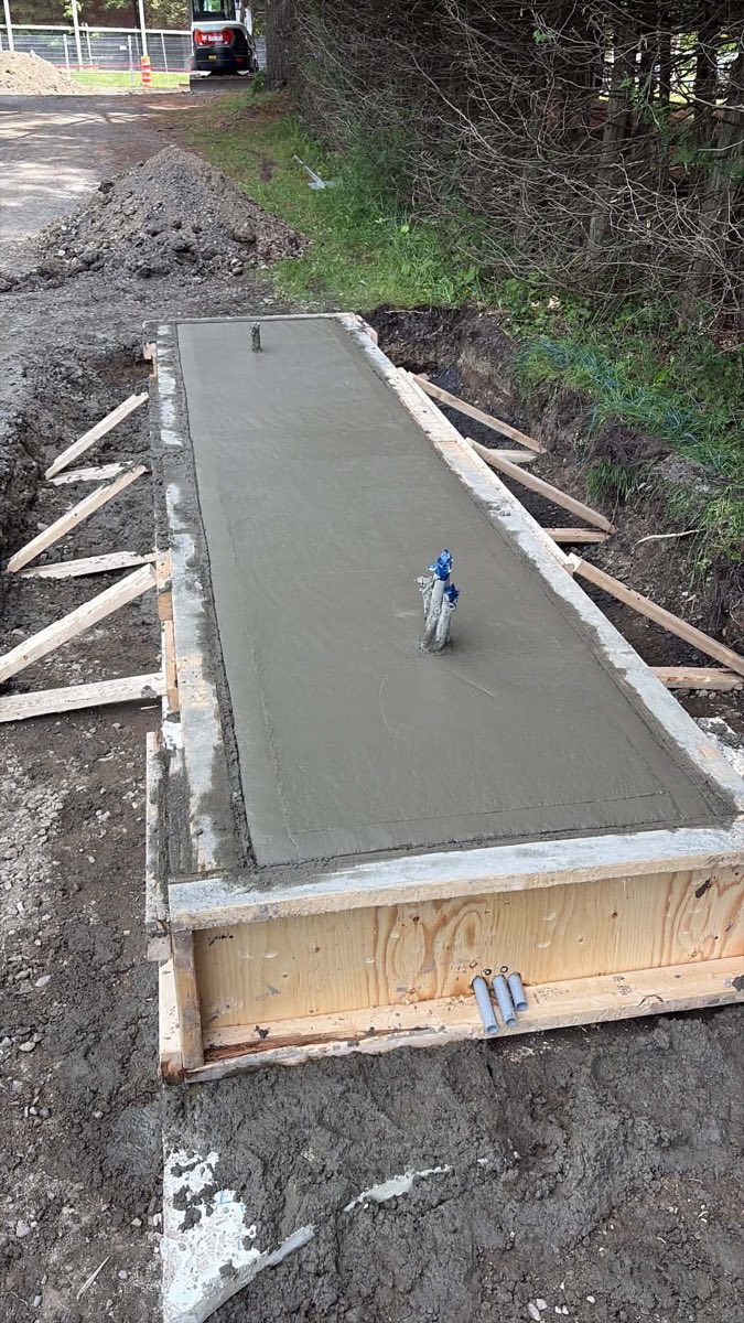
The base matters as much as the arm.
An industrial barrier brings foundations, power, controls and maintenance access into the same installation.
-
Foundation
Locate the anchor base and conduits using the selected model’s drawings.
-
Vehicle clearance
Allow for the vehicles using the lane and the arm’s movement envelope.
-
Service access
Leave space to reach the housing, connections and maintenance points.
Industrial barrier selection
| Criterion | Details |
|---|---|
| Manufacturers offered | ELKA, Automatic Systems and Pivin & Drapeau |
| Model selection | Based on clear lane width, vehicle types, traffic and operating duty |
| Arm and movement | Length, opening time and clearances confirmed for the selected model |
| Power and controls | Supply voltage, control interface and failure behaviour confirmed in the model documentation |
| Environment | Temperature and enclosure ratings confirmed for the site and selected model |
| Impact resistance | Specify separately where required; obtain the exact model’s test rating and supporting documentation |
| Maintenance | Follow the selected manufacturer’s service schedule and site duty |
Documents for the selected configuration. Before approving the equipment, obtain the exact model and regional version, dated datasheet, foundation and anchoring drawing, supply requirements, control wiring and service instructions. Manufacturer catalogues help compare families; confirm the configuration Lexoh proposes for your site.
Official manufacturer references
Project handoff
Prepare the industrial entrance brief
Give the project team a usable site brief before it selects the barrier and prices the work. Record these decisions with the offered model and installation drawings.
| Component or use | How it fits the system |
|---|---|
| Vehicles and approach | Site plan, clear lane width, largest vehicle dimensions, turning path and stopping point; include delivery vehicles and trailers. |
| Operating demand | Peak arrivals and departures, expected opening cycles, shift changes and space available for waiting vehicles. |
| Access workflow | Staff credentials, visitor or delivery authorization, operator responsibilities and the action expected when access is denied. |
| Existing infrastructure | Manufacturer/model references, control diagrams, foundations, conduits and available power/network connections to be assessed for reuse. |
| Delivery responsibilities | Assign civil work, wiring, barrier installation, detection, software setup, commissioning and support. Identify who supplies each approved drawing. |
| Acceptance and handover | Agree on representative vehicle tests, approved protective-device checks, operator training, outage procedures and service documents before handover. |
Configuration: This brief defines the project; the selected manufacturer’s drawings and ratings define the equipment.
Equipment questions
Practical details for planning, operating and maintaining this equipment.
Use the first installation as a documented reference, then check the new entrance independently. Keep the equipment references, operating sequence and service records, but reassess foundations, clearances, vehicle paths, power and controls for the new site. Similar-looking entrances do not establish identical installation requirements or the suitability of the same model.
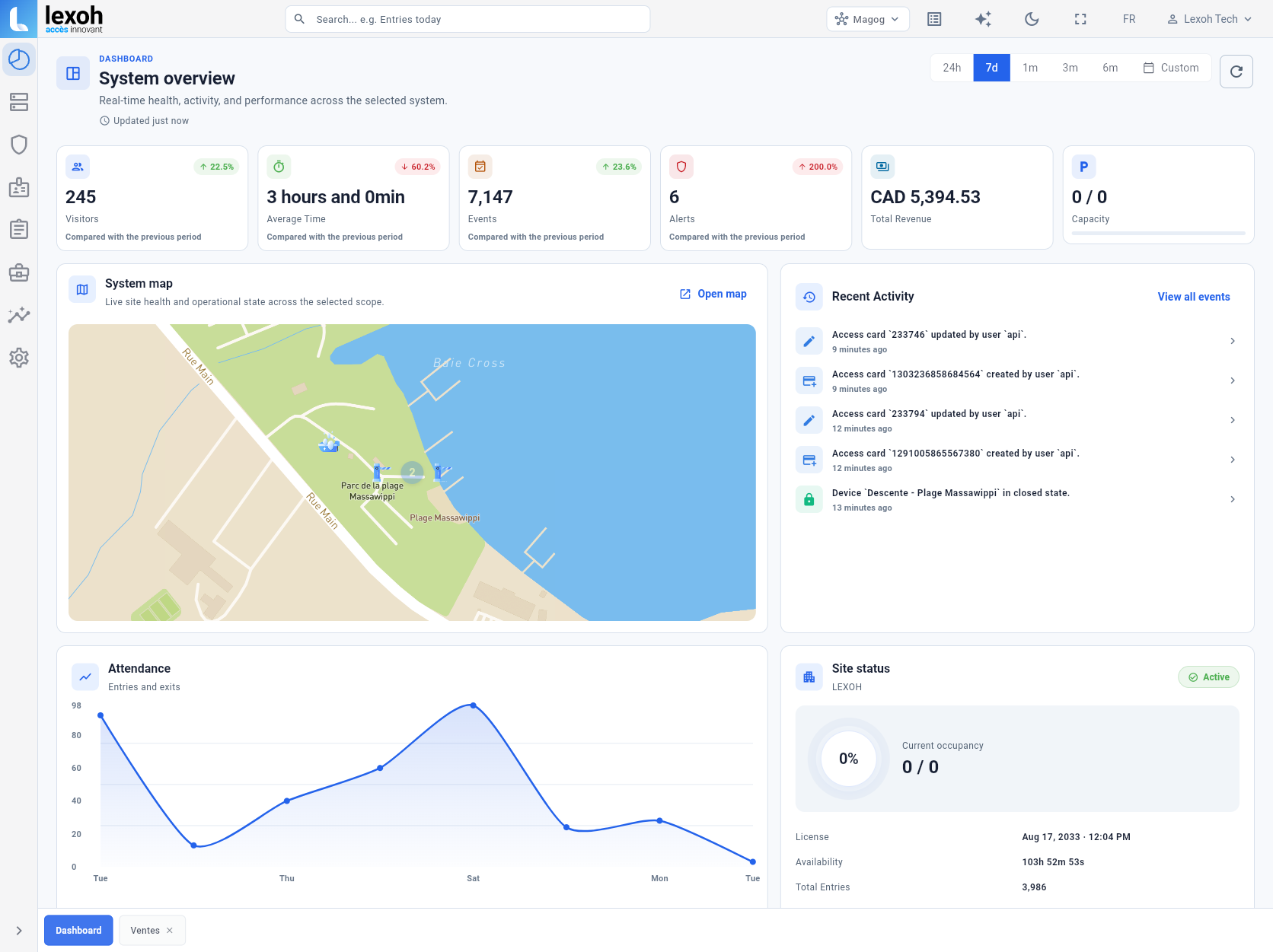
Lexoh combines cloud management with an offline mesh network that lets site devices communicate without internet. Barrier movement also depends on electrical power, the selected controller and configured access rules. Local device communication, remote operator access and power-loss procedures are separate parts of the commissioning plan.
Project review
Plan your industrial entrance with Lexoh.
Send the site plan, truck and delivery requirements, peak operating periods, existing equipment references and installation schedule. Lexoh can review the barrier, control interfaces and responsibilities with your installation team.