




A boom barrier controls a shared entrance or exit lane. An individual space blocker reserves one parking bay. Choose according to where authorization must be checked: at the site entrance or at a particular space. This page covers lane barriers; selection includes the arm, vehicle detection, access controls and the complete passage sequence.
Barriers and lane equipment
Automatic parking barriers for vehicle access
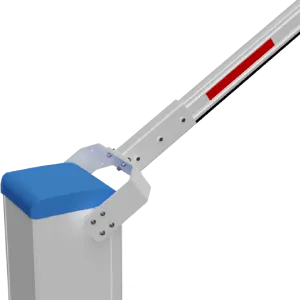
An automatic parking barrier uses a lifting arm to control a vehicle lane. Lexoh integrates the barrier with the selected access software, readers, kiosks and detection. For owners, operators and installers, the equipment choice starts with lane width, overhead clearance and the complete arrival-to-exit workflow.
- Role
- Vehicle-lane control
- Selection
- Site and workflow specific
- Technical definition
- Approved model package
Selection logic
How do you choose an automatic parking barrier?
A barrier is selected as one part of the complete entrance. The final model, arm, services and control behavior follow the physical site and approved operational workflow.
Straight or articulated arm?
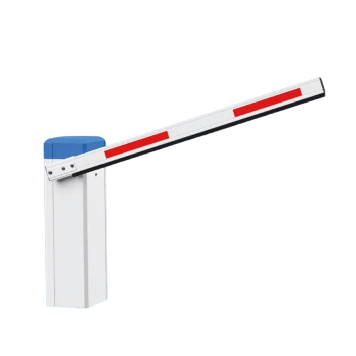
A straight arm needs clearance for its full movement. An articulated arm can suit a height-constrained entrance, subject to the selected model geometry. Measure the lane, ceiling and nearby equipment before confirming either configuration.
What controls opening and closing?
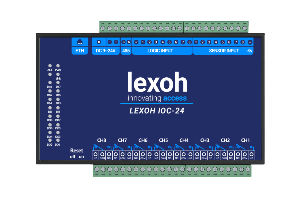
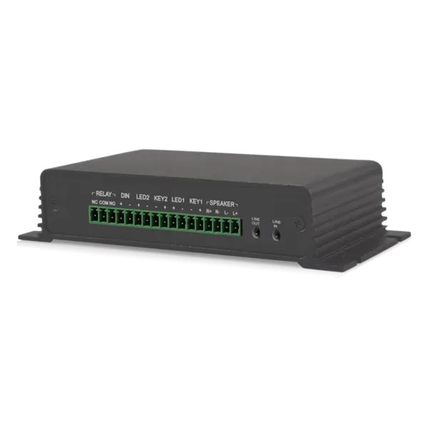
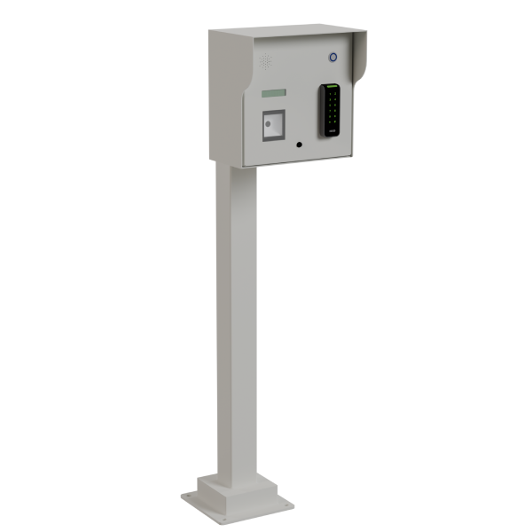
A reader or kiosk supplies an access request. The configured access system or an authorized operator issues the opening command through the controller. Vehicle detection and the specified safety devices help determine when passage and closing are permitted. These roles are configured and tested together.
Which specifications need model confirmation?
Confirm arm length, opening time, duty cycle, power, enclosure rating and operating temperature in the selected model documentation. Traffic volume, winter conditions and the required maintenance access shape the choice.
Interactive evaluation
Compare barrier forms in 3D.
Explore the shape and movement of each configuration. Request the selected model’s technical drawings to confirm installation dimensions; the viewer is a visual guide.
The product photo remains visible until you choose “Explore in 3D”. Model previews illustrate form and movement; use the offered manufacturer’s drawings for installation.
At the entrance
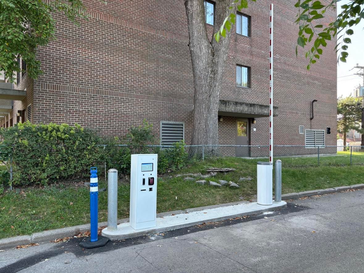
Leave room for the whole movement.
The lane layout connects the raised arm, vehicle stopping point and equipment beside the driver.
-
Before the arm
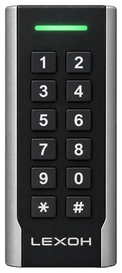
Position the reader or kiosk where the driver can stop and use it.
-
Through the lane
Coordinate presence detection and the barrier’s closing sequence.
-
Beside the housing
Keep the service access and moving parts clear of nearby equipment.
Technical Characteristics
| Specification | Details |
|---|---|
| Arm Configuration | Straight, articulated or lane-specific according to the model |
| Cycle Time | According to the model and arm length |
| Power | Confirmed with the selected model data sheet |
| Enclosure Rating | Confirmed with the selected model data sheet |
| Compatible Detection | Induction loop, above-ground detection and safety devices according to the design |
| Operating Temperature | Confirmed for the selected model and site conditions |
| Access Methods | RFID, UHF, LPR, QR, intercom, payment or control according to the system |
| Service | Installation, configuration and maintenance offered according to project scope |
Specifications confirmed by model. This page presents selection criteria, not one universal data sheet. Cycle time, arm length, power, enclosure rating, temperature range and options are confirmed in the selected model documentation and the project technical scope.
Equipment details
Prepare the lane brief for your quotation
Compare the lane requirements before choosing equipment. Include the arm’s movement, peak traffic, outdoor conditions and the way drivers identify themselves.
| Component or use | How it fits the system |
|---|---|
| Straight arm | A straight arm rises above the lane. Its movement needs clear space above and beside the entrance. |
| Articulated arm | Compare the exact fold geometry and full movement envelope with the ceiling, beams, pipes and vehicle path. Confirm the raised position and service clearance on a dimensioned model drawing before selecting the assembly. |
| Traffic and duty cycle | Record peak-period arrivals and expected opening cycles. Match the selected model’s duty rating and operating time to that demand, including queues and assistance stops. |
| Outdoor and winter conditions | Document temperature, wind exposure, drainage and snow-clearing needs. Confirm the chosen model’s environmental ratings and any required accessories for the site. |
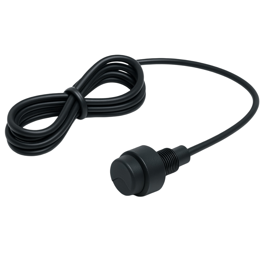
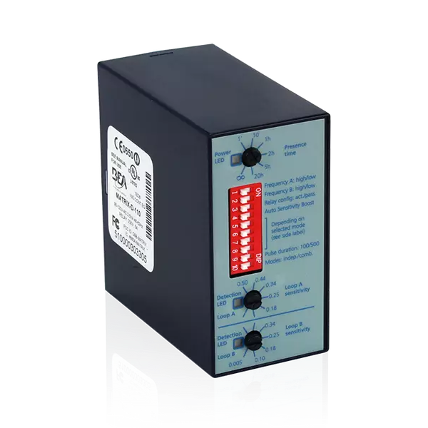
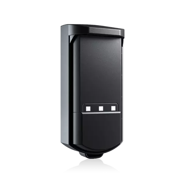
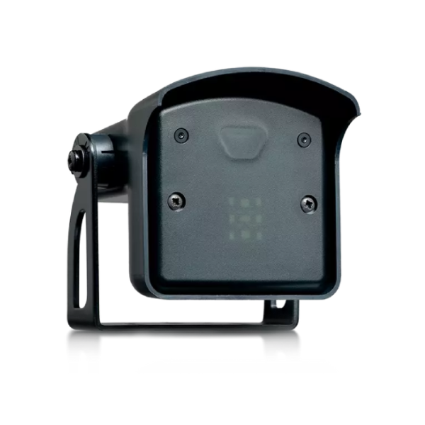
| Detection | Vehicle detection gives the lane controls information about arrival, presence or passage. Safety devices and closing behavior are designed with the barrier. |
| Access command | A reader, kiosk or operator can form part of the access sequence. The selected controls link the access decision to the barrier movement. |
| Power and outage procedures | Define what operators and drivers should do during a power or communication outage. Review power requirements, release procedures and any backup option against the selected equipment. |
| Installation documents | Request the offered manufacturer/model, dated data sheet, arm and movement drawing, base/fixing/conduit plan, electrical requirements, approved accessories and maintenance instructions. Keep the revision and approving party with the final lane plan. |
| Comparing offered configurations | For each proposal, record the exact model and arm, the required lane event, included detection, environmental limits and unresolved site work. Compare the same operating scope; a rendered arm shape is not a manufacturer specification. |
Configuration: Cycle time, arm length, environmental ratings and compatibility depend on the selected model.
Equipment questions
Practical details for planning, operating and maintaining this equipment.
Opening time measures one movement of the arm. A complete passage also includes approach, credential reading or payment, the access decision, vehicle movement and the configured closing sequence. Assistance stops and the mix of vehicles affect the queue. Evaluate the complete journey during representative traffic; an arm cycle alone does not establish a vehicles-per-hour capacity.
Measure the lane, ceiling, beams, pipes and nearby equipment, then compare them with the selected arm’s full movement envelope. Confirm the fold location, raised position, vehicle clearance and service access using the exact model drawing. A nominal ceiling height or a similar-looking 3D model does not establish that the assembly will fit.
No. A parking boom barrier controls the normal vehicle passage sequence. A specified level of vehicle-impact resistance is a separate requirement that needs evidence for the exact tested product and installation. Do not infer a crash rating from the barrier’s appearance, arm length or the word industrial; state the required purpose during the site review.
Send the barrier manufacturer and model, arm reference and length, configuration photographs and details of any fitted lights or accessories. Ask the supplier to confirm the approved replacement assembly and any adjustment or commissioning requirements for that exact model. A matching length or appearance alone does not establish compatibility; the installer should verify the completed movement and control sequence.
Review the lane when its vehicle population, reader position, payment process or surrounding layout changes. A new stopping point or larger vehicle can affect the relationship between the arm, detection and driver interaction. Record the change, check the selected equipment’s requirements and repeat the relevant commissioning checks before relying on the revised sequence.
Project review
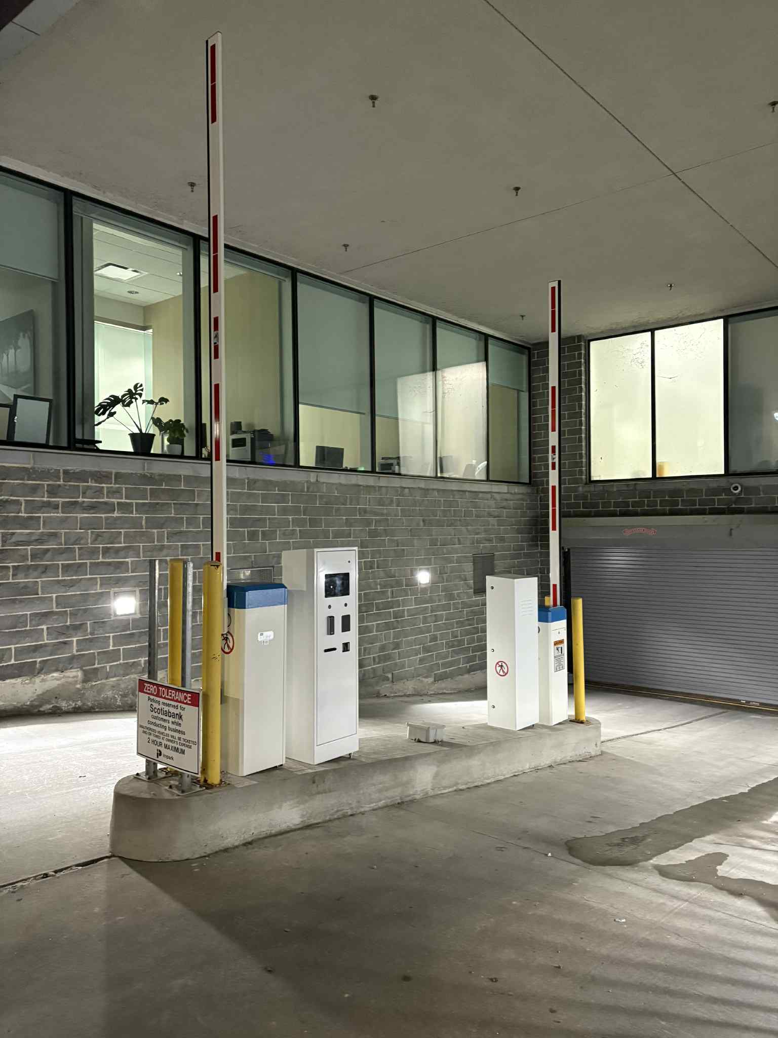
Define the lane before choosing the barrier.
Send entrance photos, clear lane width, overhead clearance, peak traffic and existing equipment references. Include the access method and any proposed arm replacement so Lexoh can review the required configuration.