

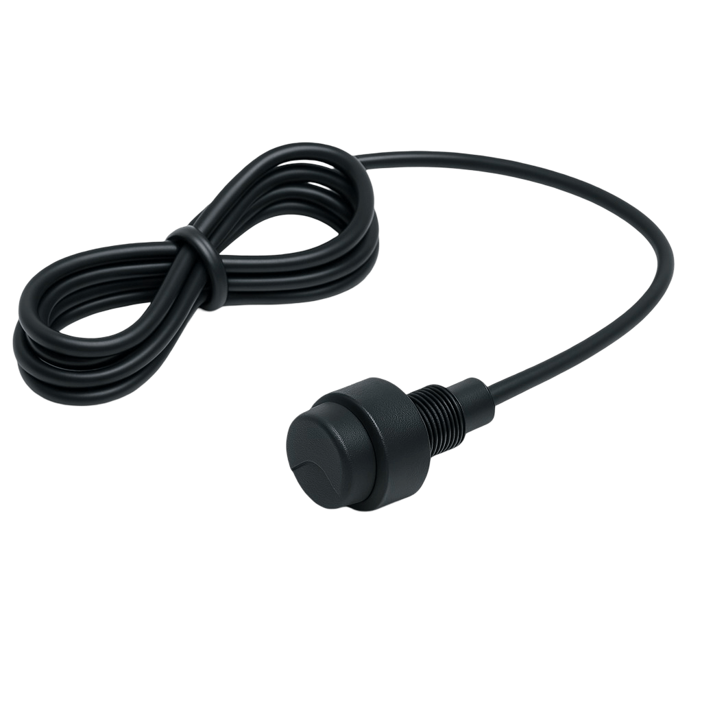
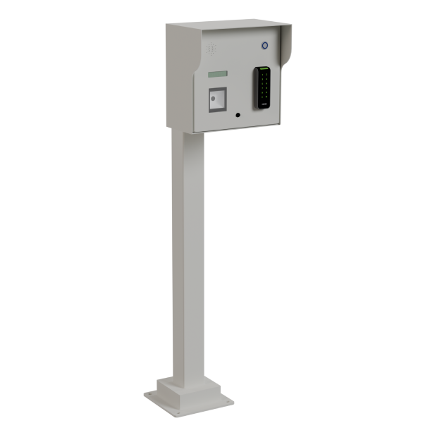

Update the point list, wiring reference and operating sequence together, recording which device and function belong to each changed input or output. Keep the previous and approved configuration references available to the service team. Test the affected signals and dependencies before handover so the physical installation, documentation and controller behavior describe the same arrangement.
Controls and interfaces
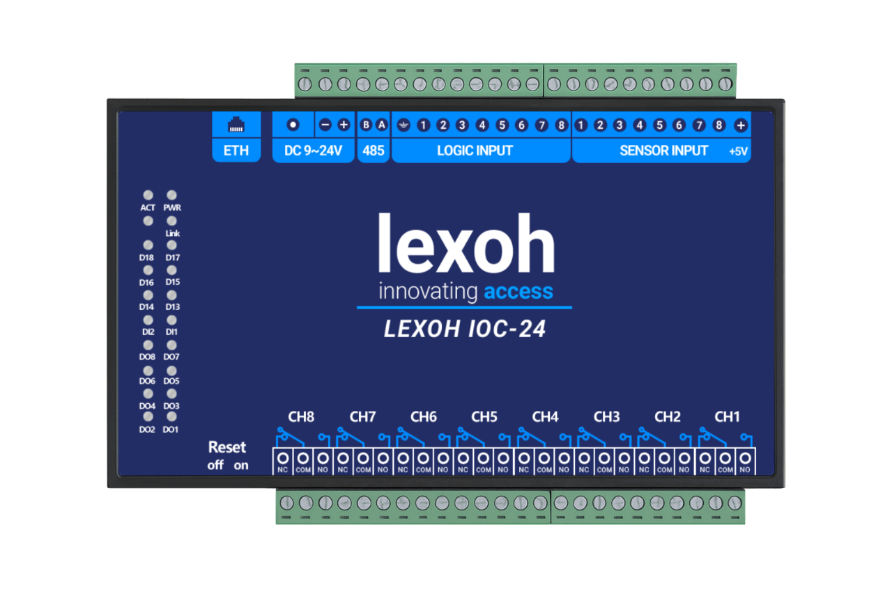
I/O controller for access equipment
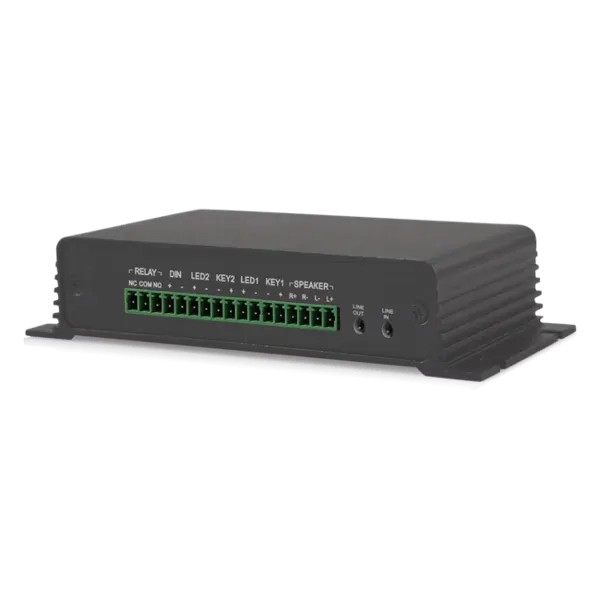
An input/output (I/O) controller receives equipment states and sends configured commands through its inputs and outputs. It connects compatible field devices to the access sequence, with wiring, electrical ratings and fault behavior defined for the installed equipment. Plan the equipment and its place in the access workflow with Lexoh.
- Role
- Field equipment interface
- Points
- Project defined
- Electrical data
- Model documentation
Sequence first
An I/O controller connects field signals to the operating sequence.
Inputs receive states from connected equipment; outputs issue configured commands. Start with the actual signals and required behavior before selecting the controller.
How many inputs and outputs are needed?
List every source, destination and required state: detection, equipment feedback, commands and any project-specific signals. Count the required points and identify their electrical characteristics. Compare that list with the selected controller’s documentation before confirming capacity.
Can any reader or barrier be connected?
No. Match interface type, voltage, wiring and output ratings to each connected device. The I/O controller does not by itself establish credential compatibility or access permissions; those depend on the approved reader and access-system architecture.
Define behavior when a signal or connection is lost
Document timing, manual operation, interlocks and the required response to power, communication or device faults. Test the controller with the real connected equipment and approved wiring. Do not assume an input or relay alone provides a safety function.
Field connections
Give every input and output a clear role.
The controller connects field states and commands through the electrical interfaces supported by its model.
-
Inputs
Identify the connected device and the state each input represents.
-
Control sequence
Define how the system uses those states, including unavailable or fault conditions.
-
Outputs
Map each command to the intended equipment and its compatible electrical interface.
I/O controller selection criteria
| Selection item | What to confirm |
|---|---|
| Input types and count | List each field signal and its electrical type, normal state and fault state. Confirm the supported inputs and available capacity for the exact controller. |
| Output type and load | Identify whether each device requires a relay contact or another supported output. Verify voltage, current, load type and any interface equipment against both devices’ documentation. |
| Power and enclosure | Confirm the controller supply, connected loads, enclosure and mounting arrangement. The complete electrical design must account for the equipment actually installed. |
| Communications and permissions | Confirm the supported connection to the access system, responsibility for operating rules and permitted commands. A network connection alone does not establish integration. |
| Loss and restart behavior | Define the required response to power loss, unavailable communications and a failed field device. Verify startup and recovery behavior with the selected equipment. |
| Installation documentation | Obtain the exact model’s dimensions, environmental limits, terminal diagram and instructions. Retain the approved point list and tested configuration with the site records. |
Request the current datasheet, connection diagram and approved configuration for the exact equipment proposed in your quotation.
Prepare the control package
Bring the point list and sequence to the project discussion
Lexoh needs the field equipment, required behavior and existing installation details to assess the controller within the complete access system.
| Planning item | Information to provide |
|---|---|
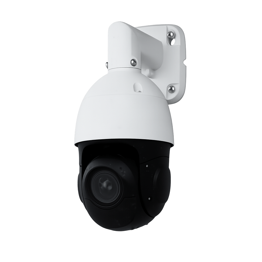
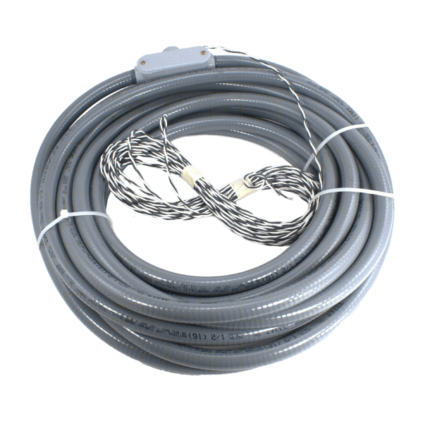
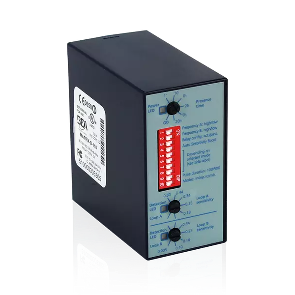
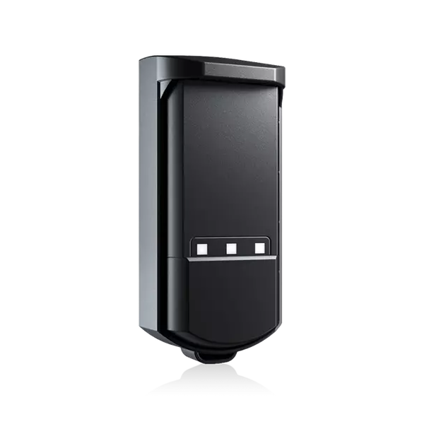
| Connected equipment | List the barriers, detectors, readers and feedback devices involved. Include exact references and available wiring diagrams for equipment you intend to retain. |
| Point schedule | For each signal, record its source or destination, normal and fault states, electrical type and intended function. Mark the points reserved for a planned expansion. |
| Operating sequence | Describe normal entry, refused entry, manual operation and loss of power or communications. Identify the person responsible for approving the required behavior. |
| Acceptance and handover | Agree on the checks for each point, command and available feedback. Record configuration versions, final drawings and the maintenance contact after commissioning. |
Configuration: Keep the approved equipment references, configuration and test results with the site records.
Equipment questions
Practical details for planning, operating and maintaining this equipment.
No. A command shows that an action was requested; confirming physical movement requires the feedback or observation defined for the installation. Identify which equipment states are available and how operators should interpret them. Test a normal action and the agreed failure cases rather than treating an output change as proof that the lane is open.
Project review
Plan the connections for your entrance.
Share the connected equipment, available wiring diagrams and required operating sequence. Lexoh can review the inputs, outputs and controller requirements for your site.